
Custom Motor Shaft Manufacturer: Precision CNC Turning & Machining for Electric Motors
Short answer: A custom motor shaft manufacturer produces precision turned and ground shafts for electric motors — including EV traction motors, industrial servo motors, HVAC blower motors, and aerospace actuators. VOLCRIX machines motor shafts on Swiss-type lathes and CNC turning centers, with tolerances to ±0.01 mm and surface finishes to Ra 0.4 μm. Materials include 4140, 4340, 17-4PH, and SUS303 stainless, with annual volumes from 1,000 to 500,000 pieces and PPAP Level 3 documentation as standard.
Common Applications We Support
- EV traction motor shafts — rotor shafts for permanent magnet and induction motors used in 400V and 800V drive units. Balanced to ISO 1940 G2.5 at rated speed (typically 16,000–20,000 rpm).
- Industrial servo motor shafts — for precision servo motors used in robotics, CNC machinery, and automated assembly lines. Tight concentricity (≤ 0.005 mm TIR) and surface finish to Ra 0.2 μm on encoder mounting surfaces.
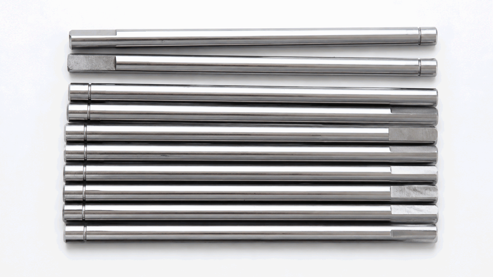
- HVAC blower motor shafts — for residential and commercial HVAC blower motors, typically 6–12 mm diameter with simple keyway or D-cut features. High-volume, cost-sensitive.
- Aerospace actuator shafts — for flight control actuators and landing gear systems. AS9100-grade documentation, full material traceability, and 100% dimensional inspection on every piece.
How VOLCRIX Supports Your Motor Shaft Program
- Swiss-type turning for diameters 1.5–32 mm. Single-setup accuracy of ±0.005 mm and full-length concentricity within 0.01 mm TIR — critical for slender rotor shafts that would deflect on a standard lathe.
- Multi-axis CNC turning for diameters up to 200 mm. Live tooling, C-axis milling, and Y-axis off-center drilling for complex features on larger motor housings and shaft assemblies.
- Cylindrical grinding for bearing journals. Studer and Okamoto precision grinders deliver Ra 0.2 μm finish and roundness within 0.002 mm on bearing journals and sealing surfaces.
- Dynamic balancing and runout verification. Schenck and Hofmann balancing machines verify rotor balance to ISO 1940 G2.5 at rated speed, with single-plane and two-plane correction as required.
Motor shafts are unforgiving. A 0.01 mm runout at the encoder mounting surface becomes 0.1 mm at the end of a 100 mm shaft, which is enough to throw off position feedback on a precision servo. We control runout at every operation — between rough and finish turning, between milling and grinding, between grinding and balancing. It is not glamorous work, but it is the difference between a motor that runs true and a motor that vibrates itself apart.
Materials and Heat Treatment
| Material | Typical Use Case | Heat Treatment | Surface Hardness |
|---|---|---|---|
| 4140 alloy steel | Industrial motor shafts, general purpose | Quench & temper | 28–34 HRC |
| 4340 alloy steel | High-stress motor shafts, EV traction | Q&T + stress relieve | 32–38 HRC |
| 17-4PH stainless (SUS630) | EV traction, corrosion-sensitive | H1025 / H1075 aging | 32–42 HRC |
| SUS303 stainless | Non-magnetic applications | Solution annealed | ≤ 200 HB |
| SUS304 stainless | Food-grade, medical motor shafts | Solution annealed | ≤ 200 HB |
| Duplex 2205 | Coolant pump shafts, marine | As-machined | ≤ 280 HB |
| Silicon steel (50W470) | Laminated rotor cores (stamped) | Annealed | ≤ 180 HB |
For EV traction motors running above 16,000 rpm, 17-4PH stainless is increasingly the material of choice. It combines high strength (up to 42 HRC after aging) with corrosion resistance and non-magnetic behavior — important for motors where stray magnetic fields would degrade performance. For industrial servo motors, 4140 is the workhorse grade — predictable, machinable, and heat-treatable to the right hardness for bearing journals.
Tolerances, Surface Finish, and Inspection
Motor shaft tolerances are tighter than most precision machining because the part has to balance, run true, and survive high-RPM operation. Here is what we publish and measure:
- Diameter tolerances: ±0.01 mm on bearing journals; ±0.005 mm on ground sealing surfaces; ±0.02 mm on general features.
- Concentricity / runout: ≤ 0.005 mm TIR on bearing journals to datum A; ≤ 0.01 mm TIR on features relative to the grinding axis; ≤ 0.02 mm TIR end-to-end.
- Surface roughness: Ra 0.4 μm on bearing journals after precision grinding; Ra 0.2 μm on encoder mounting surfaces; Ra 0.8 μm on general machined surfaces.
- Dynamic balance: ISO 1940 G2.5 at rated speed for rotor shafts; single-plane correction for short rotors, two-plane for long rotors.
- Keyway / D-cut tolerances: ±0.02 mm on width; ±0.05 mm on depth; ±0.1 mm on position.
- Spline tolerances: Class 7 to DIN 5480 / ISO 4156 for involute splines; class A fit on parallel keys.
Our inspection workflow uses a Renishaw Equator gauge for fast dimensional checks during production runs, a Zeiss CMM for first-article inspection and capability studies, and a portable spectrometer (Hitachi X-MET) for incoming material verification. Balancing is performed on a Schenck or Hofmann machine with calibration traceable to national standards. Every shipment includes an FAI report, a control plan, and the CMM measurement log in PDF format.
Process Selection: Swiss Turning vs. CNC Turning vs. Cylindrical Grinding
Motor shafts typically require multiple operations. Here is the typical sequence and why each step matters:
- Rough turning — removes 80% of the material on a CNC turning center or Swiss lathe. High material removal rate, low precision requirement. We typically hold ±0.05 mm on rough features.
- Finish turning — brings the part to ±0.02 mm on all critical features. Uses the same machine as rough turning but with finer feeds and sharper tooling.
- Milling (if required) — adds flats, slots, keyways, or cross-drilled holes. Performed on live-tool Swiss lathes for diameters under 32 mm; on a separate CNC mill for larger diameters.
- Cylindrical grinding — brings bearing journals to Ra 0.2 μm and roundness within 0.002 mm. Performed on Studer or Okamoto precision grinders with in-process gauging.
- Dynamic balancing — verifies rotor balance to ISO 1940 G2.5 at rated speed, with material added or removed to achieve the required residual unbalance.
- Final inspection — 100% dimensional verification on critical features, with CMM spot checks every 50 pieces for capability verification.
For very high volume programs (above 100,000 pieces), we recommend a dedicated cell layout where the part moves from rough turning to final inspection without queuing between operations. This typically reduces cycle time by 30–40% and improves consistency.
Buyer Checklist Before You Issue the RFQ
- ☑ They hold IATF 16949 certification, not just ISO 9001. Automotive motor shaft production needs the automotive-specific QMS, not a generic one.
- ☑ They run Swiss-type lathes for slender shafts. A 5 mm diameter, 300 mm long shaft will chatter on a chucking lathe; it will not on a Swiss.
- ☑ They have a CMM and balancing machine on site, not outsourced. Critical Cpk studies and balance verification should be measured in hours, not weeks.
- ☑ They will sign your NDA and your PPAP terms before you pay them. Suppliers who want to negotiate IP after the RFQ is awarded are the wrong suppliers.
- ☑ They give you a quote in 24 hours, not 5 business days. Responsiveness on RFQ predicts responsiveness on quality escapes.
Related Custom Manufacturing Services
- Custom Precision Shafts — the parent capability page covering grinding, spline cutting, and dynamic balancing for any shaft type.
- Custom Swiss Turning Parts — for diameters 1.5–32 mm with tight tolerances and high material yield.
- Automotive Parts Manufacturing — Tier-1 capable stamping, machining, and assembly for passenger and commercial vehicles.
- CNC Machining Service — for brackets, housings, and non-shaft components in your bill of materials.
Why VOLCRIX for Custom Motor Shafts
VOLCRIX is a custom precision machining shop in Wenzhou, China, operating since 2008 under ISO 9001 and IATF 16949 quality systems. We run a 4,500 m² shop floor with 38 CNC turning centers (including 12 Swiss-type lathes), 6 CNC cylindrical grinding machines, 5 wire EDM stations, and a dedicated metrology room housing a Zeiss coordinate measuring machine plus a Hitachi X-MET portable spectrometer for incoming material verification. We also run Schenck and Hofmann balancing machines for dynamic balancing to ISO 1940 G2.5. Every production lot carries an FAI report, dimensional inspection log, and full material traceability.
Our typical lead times for motor shaft programs: 7–15 days for prototypes, 25–40 days for serial production after PPAP sign-off. We have shipped motor shafts to motor manufacturers and Tier-1 suppliers in Germany, the United States, Mexico, and Japan, with PPAP Level 3 packages accepted by all major OEMs we have audited. We hold no inventory of finished shafts — every shipment is made to order against your print, so you never inherit somebody else’s work-in-progress or material.
If you are sourcing a custom motor shaft for an EV traction motor, industrial servo, or HVAC application and want a quote within 24 hours, send your 3D model and 2D drawing to sales@volcrix.com or message us on WhatsApp. We will reply same day.
Frequently Asked Questions
What is the minimum order quantity (MOQ) for a custom motor shaft?
For prototype runs, we accept as few as 5 pieces so you can validate design and assembly fit. For serial production, MOQ is typically 500 pieces, though we have run 100-piece pilot lots for niche motor programs. Above 100,000 pieces, we enter a price-break tier.
What balance grade do you achieve on motor shafts?
Standard balancing grade is ISO 1940 G2.5 at the rated speed of the motor. For high-speed applications above 20,000 rpm we can achieve G1.0 with additional correction. We provide a balance certificate with every shipment, including the residual unbalance in g-mm and the balance grade verification.
Can you grind bearing journals after turning?
Yes. We run 6 CNC cylindrical grinders (Studer and Okamoto models) for bearing journal grinding to Ra 0.2 um and roundness within 0.002 mm. For shafts that require superfinishing or honing, we partner with a tier-1 finishing house in Shanghai under our quality control.
What is your typical lead time for prototype motor shafts?
Standard prototype lead time is 7-15 working days from PO. For expedited programs with fewer than 20 pieces and no special grinding, we can deliver in 5-7 days. Lead time depends on material availability — we stock 4140, 4340, and 17-4PH, but exotic grades may add a week for sourcing.
Certifications and Standards
- ISO 9001:2015 — Quality Management System
- IATF 16949:2016 — Automotive Quality Management
- ISO 14001:2015 — Environmental Management System
- CE Marking — European Conformity for relevant product lines
- RoHS Compliance — Restriction of Hazardous Substances
- REACH Compliance — EU chemical safety regulation
- EN 10204 3.1 — Material certification for metallic products
- ISO 1940-1 — Balance quality for rotating machinery (G2.5 standard)