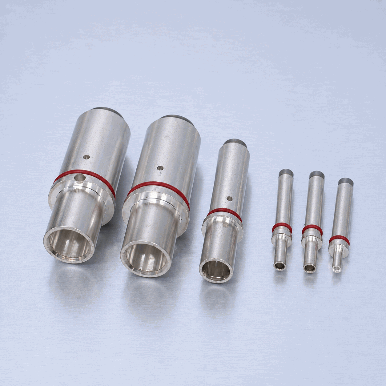

Temperature Rise in EV Charging Pins: Thermal Management for High-Power Charging
Temperature rise in EV charging pins: thermal management strategies for high-current DC fast charging. Understand how pin design, material, and cooling affect heat generation.
Ready to Start Your Project?
Free DFM review · Quote within 24 hours · Prototype in 7–15 days
Physics of Heat Generation in Charging Pins
Heat generation in a charging pin follows the fundamental Joule heating equation:
P = I² · R
Where P is the power dissipated as heat (in watts), I is the current (in amperes), and R is the total resistance (in ohms) of the current path through the pin and its mating interface.
For a typical CCS1 connector carrying 350 A, a pin assembly with 0.5 mΩ total resistance generates:
P = 350² × 0.0005 = 61.25 W
This 61 W of heat must be conducted away through the pin body, cable lug, housing, and ambient air — or actively removed via liquid cooling. The total resistance comprises two components:
- Bulk resistance of the pin material itself (proportional to resistivity × length / cross-sectional area)
- Contact resistance at the mating interface between the pin and receptacle
In high-power connectors, contact resistance often dominates the total, especially as surfaces degrade over repeated mating cycles.
Thermal Limits Per Standards
Two key international standards govern the allowable temperature rise in EV charging connectors:
UL 2251 (Plugs, Receptacles, and Couplers for Electric Vehicles)
- Maximum temperature rise: 50 K above ambient at a rated current test conducted at 40 °C ambient
- This means the maximum absolute pin temperature under test is 40 °C + 50 K = 90 °C
- Covers both AC and DC charging connectors for North American markets
IEC 62196-2 (Plugs, Socket-Outlets, Vehicle Connectors and Vehicle Inlets)
- Accessible surface temperature rise: 30 K maximum
- Internal component temperature rise may be higher but must not degrade materials or solder joints
- Governs Type 1, Type 2, and related connector systems for global markets
Exceeding these limits triggers protective derating in the charging station, slows charging speed, and — in sustained over-temperature scenarios — risks melting connector housings, welding contacts, or causing fire.
Material Thermal Conductivity Comparison
The choice of pin material directly determines how efficiently heat is conducted away from the contact interface. The following table compares common charging pin materials:
| Material | Thermal Conductivity (W/m·K at 20 °C) | Electrical Conductivity (% IACS) | Common Application |
|---|---|---|---|
| C11000 (ETP Copper) | 401 | 101 | High-performance charging pins, busbars |
| C18150 (CuCrZr — Chromium Zirconium Copper) | 324 | 82 | High-strength pins requiring wear resistance |
| CW617N (Brass — Leaded) | 115 | 27 | Low-cost standard pins, moderate power |
| SS304 (Stainless Steel) | 16 | 2.5 | Structural components only (not current-carrying) |
C11000 ETP copper delivers the highest thermal conductivity at 401 W/m·K, making it the preferred choice for high-power DC charging pins. C18150 offers a strong compromise between conductivity (324 W/m·K) and mechanical strength, useful where repeated mating cycles demand wear resistance. Brass CW617N is suitable only for lower-power AC applications (≤ 22 kW). Stainless steel should never be used for current-carrying pins due to its poor thermal and electrical conductivity.
How Pin Geometry Affects Temperature
Pin geometry plays a decisive role in thermal performance. The key geometric parameters include:
Outer Diameter (OD)
A larger OD increases the cross-sectional area for both current conduction and heat flow, reducing bulk resistance and improving thermal path. However, larger pins require larger mating receptacles and increase connector size.
Wall Thickness (for Hollow Pins)
Many high-power charging pins are manufactured as hollow tubes to reduce weight while maintaining surface area. Wall thickness directly determines the conduction cross-section: a 1.5 mm wall carries significantly less current than a 3.0 mm wall at the same OD.
Surface-to-Volume Ratio
A higher surface-to-volume ratio improves natural and forced convection cooling. Ribbed or finned pin geometries are sometimes used in air-cooled designs, though they complicate the mating interface.
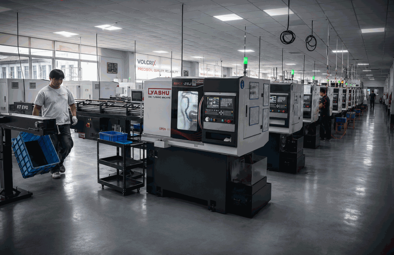
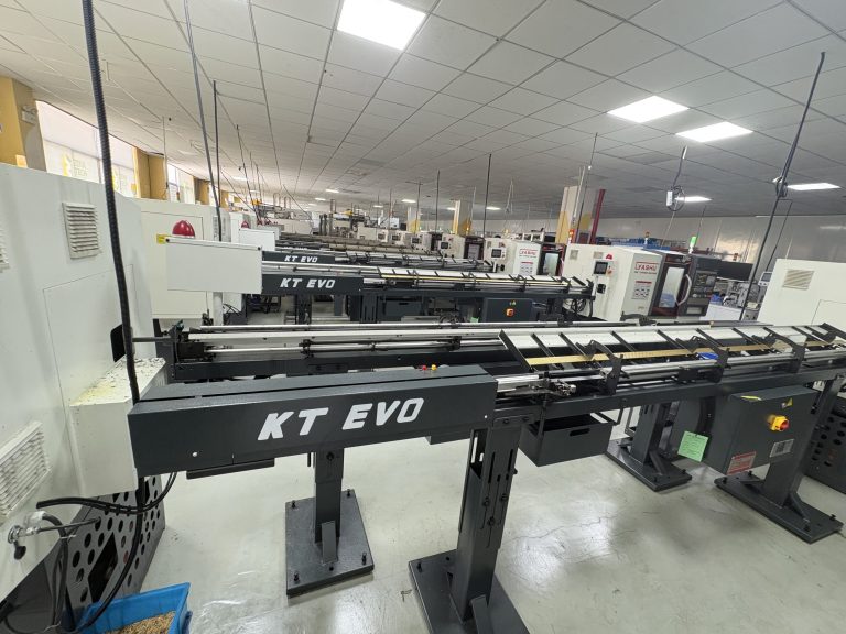
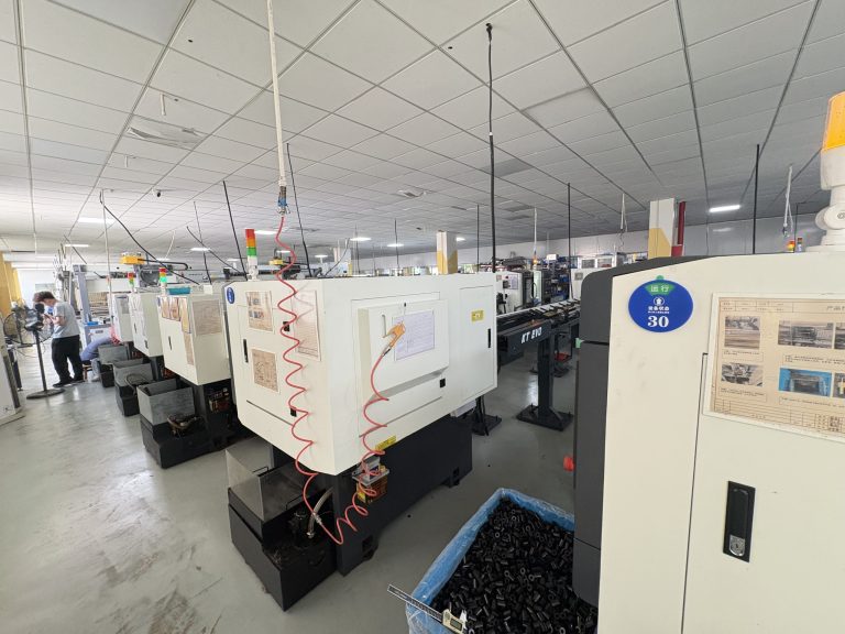
VOLCRIX precision Swiss turning enables tight tolerances on OD, wall thickness, and surface finish — all of which directly affect the thermal and electrical performance of the finished pin.
Contact Resistance and Its Thermal Impact
Contact resistance at the pin-to-receptacle interface is often the single largest contributor to overall resistance. For high-power EV charging, engineers target < 0.5 mΩ initial contact resistance per pin pair.
The consequences of elevated contact resistance are severe:
- At 0.5 mΩ: Acceptable; 350 A produces 61 W of heat at the interface
- At 1.0 mΩ: Heat doubles to 122 W — significant temperature rise
- At 2.0 mΩ: Heat reaches 245 W — rapid thermal runaway risk
Contact resistance increases over time due to:
- Oxidation — copper oxide layers act as insulators
- Fretting corrosion — micro-motion wears through plating
- Contamination — dust, oil, or moisture ingress
- Plating wear — silver or nickel plating degrades with repeated mating
Silver plating (2–5 µm) is commonly applied to high-power charging pins to maintain low contact resistance through thousands of mating cycles, as silver oxide remains conductive — unlike copper oxide.
Liquid-Cooled Pin Designs for MCS and Ultra-Fast Charging
For the Megawatt Charging System (MCS) standard targeting 1.2 MW and beyond, passive cooling becomes insufficient. Liquid-cooled pin designs are now essential:
Internal Cooling Channels
The pin body is manufactured with a central or eccentric bore through which dielectric coolant flows. Heat is conducted from the outer contact surface through the pin wall and into the flowing coolant, which carries it away to a radiator or chiller.
Tube-in-Pin Designs
A coaxial design where coolant flows through an inner tube, returns through an annular gap, or circulates through a closed-loop channel within the pin wall. These designs maximize heat transfer surface area while maintaining the required electrical contact geometry on the outer surface.
Liquid-cooled pins can reduce bulk pin temperature by 40–60% compared to equivalent passive designs, enabling continuous operation at 500 A to 1000+ A without exceeding the 50 K rise limit. The trade-offs include system complexity, coolant pump reliability, and the need for leak-proof seals at the connector interface.
Thermal Testing and Validation
Verifying thermal performance requires rigorous testing:
Thermocouple Placement
Type K thermocouples are embedded at critical locations: the pin tip (hottest point), mid-body, cable lug interface, and housing interior. Temperature is recorded under steady-state rated current per UL 2251 or IEC 62196-2 test protocols.
Thermal Imaging (IR Camera)
Infrared cameras provide full-field temperature mapping of the connector assembly during charging. This reveals hot spots not captured by discrete thermocouples — such as uneven contact pressure or localized plating degradation.
IR Camera Inspection in the Field
Periodic IR inspection of installed charging stations identifies connectors approaching the thermal limit before failure occurs. A pin running 10–15 K hotter than its paired pins indicates a contact resistance problem requiring maintenance.
FAQ
What is the maximum allowable temperature rise for EV charging pins?
Per UL 2251, the maximum allowable temperature rise is 50 K above a 40 °C ambient temperature, giving an absolute maximum of approximately 90 °C at the pin under rated current. IEC 62196-2 limits accessible surface temperature rise to 30 K. These limits protect connector materials and ensure safe operation throughout the connector’s rated life.
Does silver plating reduce charging pin temperature?
Silver plating reduces temperature indirectly by lowering contact resistance. Silver has high electrical conductivity and its oxide remains conductive — unlike copper oxide, which is an insulator. A 2–5 µm silver plate can maintain contact resistance below 0.5 mΩ over thousands of mating cycles, preventing the excessive I²R heating that would occur with oxidized copper surfaces. Lower heat generation means lower pin temperature at any given current.
What causes temperature rise besides current?
Several factors contribute beyond the current level: contact resistance (dominated by plating condition and mating force), ambient temperature (higher ambient reduces the thermal gradient available for cooling), connector housing material (plastics insulate vs. active cooling), cable lug termination quality (a poor crimp adds an extra resistance point), and cooling method (passive vs. forced air vs. liquid). Any of these can double or triple the temperature rise at the same current.
Can liquid cooling eliminate the need for copper pins?
No. Even with liquid cooling, the pin must still conduct current efficiently. Copper’s high electrical conductivity (101% IACS) minimizes I²R losses regardless of cooling method. If a lower-conductivity material (e.g., brass or aluminum) were used, the internal heat generation would be higher, and even liquid cooling might not remove the heat fast enough from the contact interface. Liquid cooling reduces bulk temperature but does not reduce contact resistance or bulk I²R losses. High-conductivity copper remains essential for the pin body.
Need charging pins designed for high-power applications? Contact VOLCRIX for thermal-optimized pin designs →
Ready to Start Your Project?
Free DFM review · Quote within 24 hours · Prototype in 7–15 days
Need custom EV charging pins for your project? View our EV charging pins manufacturing capabilities →