

Injection molded plastic parts are governed by shrinkage in a way that machined metal parts are not. A cavity cut to 50.00 mm does not produce a 50.00 mm part. The plastic cools, crystallizes, and contracts. The difference between the cavity dimension and the final part dimension is shrinkage, and it varies by material, wall thickness, fill direction, and processing conditions.
This guide covers the standard tolerance classifications for injection molded parts, shrinkage values for common engineering plastics, and the design practices that separate precision molders from commodity shops.
Ready to Start Your Project?
Free DFM review · Quote within 24 hours · Prototype in 7–15 days
Tolerance Standards
The plastics industry recognizes three tolerance classes, defined in DIN 16901 and ISO 20457. These standards assign achievable tolerances based on the cavity dimension range and the material’s shrinkage behavior.
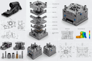
DIN 16901 classifies tolerances into three groups:
Fine. Achievable with tight process control, steel molds with hardened cavities, and materials with consistent shrinkage. Typical applications: precision housings, connector bodies, medical device components. Dimensional tolerance is roughly plus or minus 0.15 percent of the nominal dimension.
Medium. Standard commercial tolerance for most injection molded parts. Attainable with well-maintained production tooling and properly characterized materials. Dimensional tolerance is plus or minus 0.3 percent.
Coarse. Wide tolerance for non-critical dimensions. Suitable for parts where fit and finish are secondary to cost. Dimensional tolerance is plus or minus 0.5 percent or more.
For a 50 mm dimension on a precision part, these translate to:
- Fine. Plus or minus 0.08 mm.
- Medium. Plus or minus 0.15 mm.
- Coarse. Plus or minus 0.25 mm.
VOLCRIX produces tooling to fine tolerance class for custom injection molded parts, with cavity dimensions verified by CMM before first shot.
Material Shrinkage Rates
Shrinkage is expressed as a percentage of the mold cavity dimension. The values below are for typical wall thickness (2.0-3.0 mm) in a well-controlled process.
ABS. Shrinkage 0.4-0.7 percent. Moderate, predictable. Shrinkage varies with rubber content. High-impact grades trend toward the upper end.
Nylon 6 (PA6). Shrinkage 1.0-1.6 percent. Higher than most engineering plastics. Moisture content before molding significantly affects the final dimension. Dried to below 0.2 percent moisture before processing.
Nylon 66 (PA66). Shrinkage 1.2-2.0 percent. The additional methylene groups increase crystallinity, driving higher shrinkage. Glass-filled grades reduce shrinkage to 0.3-0.8 percent.
Polycarbonate (PC). Shrinkage 0.5-0.7 percent. Low, consistent. Less sensitive to wall thickness variation than semi-crystalline materials.
PBT. Shrinkage 1.2-2.0 percent. Similar to nylon. Glass-filled PBT shrinks 0.3-0.8 percent. Unfilled grades require careful gate placement to control warpage.
POM (Acetal). Shrinkage 1.8-2.5 percent. High shrinkage. Highly crystalline. Prone to warpage in asymmetric geometries. Shrinkage is strongly directional in the flow direction versus transverse direction.
LCP (Liquid Crystal Polymer). Shrinkage 0.1-0.5 percent. Extremely low. Anisotropic shrinkage in the flow direction can differ from cross-flow by a factor of 10. Mold design must account for this.
PEEK. Shrinkage 0.6-1.2 percent. High-temperature semi-crystalline. Shrinkage is mold-temperature dependent. Requires hot mold surfaces (160-200 C) for optimal crystallinity.
For insert molding applications where a metal component is encapsulated by plastic, the shrinkage differential between the two materials creates residual stress. The plastic shrinks onto the metal insert, generating compressive hoop stress. This can be beneficial (creating a mechanical lock) or detrimental (causing stress cracking in the plastic), depending on the material pair and geometry.
Factors That Affect Final Dimensions
Wall thickness variation is the single largest cause of dimensional variation in injection molded parts. A 1.0 mm wall shrinks less than a 3.0 mm wall in the same material because the cooling rate differs. The core of a thick section remains molten longer, allowing more crystallization and therefore more shrinkage.
Fill direction matters. Polymer molecules and fiber reinforcements orient in the flow direction. Shrinkage parallel to flow is typically 30-50 percent higher than shrinkage perpendicular to flow in glass-filled materials. This anisotropy must be accounted for in the cavity design.
Processing conditions affect shrinkage within the published range. Higher melt temperature increases shrinkage. Higher injection pressure reduces shrinkage by packing more material into the cavity. Longer hold time reduces shrinkage up to the point where the gate freezes. A molder that controls these variables within tight bands produces consistent parts.
Mold temperature is the most influential processing parameter for semi-crystalline materials. A 10 C increase in mold temperature can increase shrinkage by 0.1-0.2 percent for nylon and POM. Steel molds with conformal cooling channels maintain uniform mold temperature across the cavity surface, reducing part-to-part variation.
Draft Angles
Draft is required on all vertical walls perpendicular to the mold opening direction. The required angle depends on the material and texture depth.
- For unfilled engineering plastics. 0.5 to 1.0 degrees per side.
- For glass-filled materials. 1.0 to 2.0 degrees per side. Filled materials abrade the mold surface faster and require more draft for reliable ejection.
- For textured surfaces. Add 1.0 degree per 0.025 mm of texture depth.
Insufficient draft causes part sticking, ejection pin marks, and dimensional distortion. VOLCRIX evaluates draft during the mold design review and recommends adjustments before steel is cut.
Gate Type and Location
Gate design determines how the cavity fills and where the hold pressure is applied. For precision parts, the following rules apply:
Edge gates are suitable for flat parts with moderate tolerance requirements. The witness mark is visible on the part edge.
Pinpoint gates leave a small vestige on the part surface and are preferred for cosmetic applications. Gate diameter 0.5-1.5 mm depending on material and wall thickness.
Submarine (tunnel) gates automatically shear during ejection. Used for high-volume production where automatic operation is required. The gate vestige is below the part surface.
For insert molding, the gate should be positioned to direct flow around the insert rather than directly against it. Flow front impingement can displace the insert or cause flash around the insert boundary.
Gate location also determines the weld line positions. Weld lines occur where flow fronts meet after splitting around a core or insert. Weld line strength is typically 30-50 percent of the bulk material strength. For parts where structural integrity is critical, mold filling analysis is recommended before committing to a gate location.
Shrinkage Compensation in Mold Design
The mold cavity is cut oversized by the shrinkage factor. For a 100.00 mm part dimension in unfilled nylon 6 (shrinkage 1.4 percent), the cavity dimension is 101.40 mm.
The complication is that shrinkage is rarely isotropic. Flow-direction shrinkage differs from cross-flow shrinkage. Mold designers apply separate shrinkage factors for the x, y, and z axes when the material exhibits anisotropic behavior. LCP and glass-filled nylons require this treatment.
For insert molding, the cavity is cut to accommodate the insert volume plus the plastic shrinkage around it. The insert itself does not shrink at the same rate. The resulting stress can be estimated using a bimetallic beam model. If the stress exceeds the material’s yield strength, the insert is likely to cause cracking over the part’s service life.
Inspection and QC
Production injection molded parts are inspected to the tolerance class specified on the drawing. Measurement methods include:
First article inspection. Full dimensional layout using CMM or optical comparator. Verifies all critical dimensions against the drawing before production release.
In-process sampling. At prescribed intervals (typically every 2-4 hours), a sample is pulled and checked for critical dimensions, weight, and visual defects.
SPC charting. Key dimensions are tracked on X-bar and R charts. Process capability (Cp, Cpk) is reported when required.
VOLCRIX holds ISO 9001 certification for injection molding operations. Mold tooling is produced in-house with in-process inspection at each machining stage. Part inspection is performed on Zeiss CMM equipment with full dimensional reporting.
Custom injection molded parts can be produced in volumes from prototype quantities (50-500 pieces) through full production. Mold lead time is 4-6 weeks for single-cavity tools, 6-8 weeks for multi-cavity or family molds.
Frequently Asked Questions
What tolerance class is standard for injection molded parts?
Medium class (plus or minus 0.3 percent) is the industry standard for most commercial parts. Fine class (plus or minus 0.15 percent) requires tight process control and hardened steel tooling.
Why does nylon shrink more than ABS?
Nylon is semi-crystalline. The polymer chains align into ordered crystalline regions during cooling, which packs the material more densely and produces higher shrinkage. ABS is amorphous and does not crystallize, so shrinkage is lower and more predictable.
Can injection molded parts achieve the same tolerances as machined parts?
No. Machined metal parts routinely hold plus or minus 0.01 mm. Injection molded plastic parts, even in the fine tolerance class, typically hold plus or minus 0.05-0.10 mm on dimensions under 50 mm. The limitation is material shrinkage, not tooling precision.
What causes warp in injection molded parts?
Warp is caused by differential shrinkage: one region of the part shrinks more than another. Common causes include wall thickness variation, non-uniform mold cooling, highly oriented flow in glass-filled materials, and asymmetric gate placement.
How does glass fill affect shrinkage?
Glass fibers reduce shrinkage by providing a mechanical restraint. Unfilled nylon shrinks 1.0-1.6 percent. Glass-filled nylon (30 percent) shrinks 0.3-0.5 percent. The fibers also make shrinkage highly directional.
Frequently Asked Questions
What tolerance class is standard for injection molded parts?
Medium class (plus or minus 0.3 percent) is the industry standard for most commercial parts. Fine class (plus or minus 0.15 percent) requires tight process control and hardened steel tooling.
Why does nylon shrink more than ABS?
Nylon is semi-crystalline. The polymer chains align into ordered crystalline regions during cooling, producing higher shrinkage. ABS is amorphous and does not crystallize, so shrinkage is lower.
Can injection molded parts achieve the same tolerances as machined parts?
No. Machined metal parts routinely hold plus or minus 0.01 mm. Injection molded plastic parts, even in fine tolerance class, typically hold plus or minus 0.05-0.10 mm on dimensions under 50 mm.
What causes warp in injection molded parts?
Warp is caused by differential shrinkage. Common causes include wall thickness variation, non-uniform mold cooling, and highly oriented flow in glass-filled materials.
How does glass fill affect shrinkage?
Glass fibers reduce shrinkage by providing mechanical restraint. Unfilled nylon shrinks 1.0-1.6 percent. Glass-filled nylon at 30 percent shrinks 0.3-0.5 percent.
Ready to Start Your Project?
Free DFM review · Quote within 24 hours · Prototype in 7–15 days
Need custom injection molded parts for your project? View our precision manufacturing capabilities →