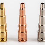

Micro Pogo Pin Manufacturing for High-Speed AI Server Interconnects
Direct answer: Micro Pogo pins are three-part spring contacts — a barrel, a spring, and a plunger — engineered to work as clean cylindrical conductors at high frequency, where stamped cantilever spring contacts break down. Published high-speed designs target 224 Gbps PAM4 at a 56 GHz baseband, with pin outside diameters from 0.2 to 0.8 mm, working heights of 1.6 to 1.85 mm, and compression travel of 0.4 to 0.6 mm. VOLCRIX manufactures the turned and formed components — barrels, plungers, and springs — on 60+ Japanese Star Swiss machines and 60 spring coilers, under ISO 9001 and IATF 16949, in Wenzhou, China since 1991.
Need Micro Pogo Pin Components Manufactured?
Barrels · Plungers · Springs · Micro-precision turned contacts · Quote in 24 hours
Why the Connector Inside an AI Server Became the Bottleneck
When a single package needs several thousand contacts and the differential pairs running through them carry a 56 GHz baseband, the mechanical structure of the contact dictates whether the link works at all. The part that gave way first was the stamped spring contact — cheap, well understood, and made on high-speed presses. It is also a bent beam, and a bent beam has properties that become liabilities at high frequency.
Three Limits That Stack Up on Stamped Contacts
| Limit | Physical Cause | Consequence at High Speed |
|---|---|---|
| Stub resonance | The cantilever bend leaves an unused conductive extension (a stub) that carries no signal | Above roughly 56 GHz the stub acts as an open resonator — reflection and insertion loss worsen sharply |
| Pitch floor | The bend needs lateral space to flex, which cannot be removed without changing the spring behaviour | Minimum pitch generally 1.0 mm or more; at several thousand contacts per package the connector area can exceed the chip itself |
| Travel compression | Lowering the stack height reduces the remaining deflection range | Going from 2.4 mm to 2.1 mm can leave only 0.3 mm of travel, while a kilowatt-class package may need 0.5 mm or more for thermal warpage |
The last two limits conflict with the first. High frequency wants a short, stub-free conductor; absorbing thermal and assembly tolerance wants travel. A stamped cantilever has to give up something on both, and in modern AI server sockets there is no longer margin to give up.
What Makes a Micro Pogo Pin Different
A Micro Pogo pin is an existing architecture pushed into a new electrical regime. The structure is familiar — barrel, spring, plunger — but every decision is subordinated to one goal: the pin must behave as a clean cylindrical conductor across a wide frequency band.
The Structural Advantage: Independent Cylindrical Contact, No Stub
- Each pin is a self-contained cylindrical conductor. There is no unused conductive extension hanging off it, so there is no open resonator to excite at high frequency. Reflection and resonance are suppressed by the geometry itself, rather than compensated for with materials or plating.
- Impedance stays continuous. A regular cylinder presents a uniform characteristic impedance along its length, which is what a differential pair needs in order to avoid return loss penalties.
- Crosstalk is structurally lower. Stamped contacts couple through their bend geometry; independent pins do not. With a sensible ground-pin allocation, near-end and far-end crosstalk fall well below what a cantilever array achieves at the same pitch.
- Pitch is not limited by lateral flex space. Each pin deflects on its own axis, so nothing needs room to bend sideways. Micro Pogo pitches have been demonstrated down to 0.35 mm, roughly a third of the stamped-contact floor.
Need Micro Pogo Pin Components Manufactured?
Barrels · Plungers · Springs · Micro-precision turned contacts · Quote in 24 hours
Published High-Speed Micro Pogo Parameters
These figures come from a published 224 Gbps Micro Pogo XPU socket design. They are design targets and simulation results from the manufacturer, not third-party measurements, and real performance depends on PCB layout, array geometry, and ground-pin allocation.
| Parameter | Published Figure | Engineering Note |
|---|---|---|
| Data rate | 224 Gbps PAM4 | 56 GHz baseband; 90 GHz capability claimed in reserve |
| Characteristic impedance | 85 ± 5% ohm | TDR measured 84-86 ohm — the standard differential range |
| Insertion loss (0-56 GHz) | ≤ -0.5 dB | Simulated; measured figures better within 61 GHz |
| Return loss (0-56 GHz) | ≤ -15 dB | Measured better than -18.5 dB within 66.5 GHz |
| Near-end crosstalk | ≤ -35 dB | Measured better than -40 dB within 60.5 GHz |
| Far-end crosstalk | ≤ -40 dB | Dense arrays are the hard case |
| Differential-to-common mode | ≤ -40 dB | Measured better than -45 dB within 63 GHz |
| Pin outside diameter | 0.2 – 0.8 mm | Signal and ground pins both in this range |
| Minimum pitch | 0.35 mm | Roughly one third of the stamped-contact floor |
| Working height | 1.6 – 1.85 mm | Total compression travel 0.4 – 0.6 mm |
| Working force | 25 gf | Narrow window — spring rate control is critical |
| Mating cycles | ≥ 100,000 | Sliding contact, so wear rather than fatigue is the failure mode |
| Current per pin | 10 – 50 A (high-current variants) | Low contact resistance and impedance-assisted thermal path |
Two Pin Configurations
| Configuration | Typical Use | Dimensions |
|---|---|---|
| Double-ended pin | Board-to-board vertical interconnect; GPU stacking; multi-die compute modules. The workhorse of XPU socket designs. | Overall length 1.85 mm; compression travel up to 0.6 mm; working force 25 gf; pitch 1.0 mm design value |
| Single-ended pin | High-speed backplanes; cable breakout from GPU modules; rack-level interconnect. One end terminates to a wire or solder tail. | Overall length 1.6 mm; compression travel up to 0.4 mm |
Manufacturing a Sub-Millimetre Spring Contact
The hard problems are not the ones the drawing calls out. A print can specify a 0.4 mm barrel with three decimal places and the part can still be unmanufacturable because tool wear at that scale outruns the tolerance band, or because a burr at the plunger shoulder bridges two contacts in a fine-pitch array.
The Four Process Steps
- Barrel. Small-diameter tube, turned or drawn, then formed and crimped to capture the spring. The crimp has to hold the spring without deforming the bore, which is the point where a marginal supplier first shows weakness.
- Plunger. Turned on Swiss-type lathes. Concentricity between the contact tip and the barrel bore is the governing dimension — eccentricity converts directly into contact resistance variation and, at 56 GHz, into impedance variation along the signal path.
- Spring. Coiled with a controlled rate. A 25 gf working force at 0.6 mm travel leaves a narrow acceptable band, so the spring rate has to be held, not merely checked.
- Assembly and inspection. Precision press-fit and crimp, then optical inspection of barrel concentricity, plunge depth, and spring force. At pin diameters below 0.5 mm, inspection is not a quality formality — it is the only way to know the part is what the drawing says.
Plating deserves its own note. At 56 GHz the skin depth in gold is a few hundred nanometres, so the signal travels in the plating, not the base metal. Plating uniformity across the contact face is a signal integrity parameter as well as a wear parameter.
What VOLCRIX Manufactures, and What We Do Not
In-House Capability
- Barrels — small-diameter tube turning, forming, and crimping
- Plungers — Swiss turning with concentricity control at sub-millimetre diameters
- Springs — 60 coiling machines with in-house rate control
- Test socket pins — machined contacts for semiconductor and high-frequency test applications
- Materials — beryllium copper, phosphor bronze, brass, stainless; hard gold over nickel plating
- Inspection — spectrometer material verification per heat lot, Zeiss CMM, optical measurement of concentricity, plunge depth, and burr condition
- Quality systems — ISO 9001:2015 and IATF 16949, with PPAP documentation available
We supply precision components to your drawing. We do not assemble finished connectors into housings and we do not carry out final high-frequency S-parameter validation of a populated socket — that belongs with the connector house that owns the electrical design.
Frequently Asked Questions
What is the difference between a Micro Pogo pin and a standard Pogo pin?
A standard Pogo pin is built around mechanical contact reliability: a barrel, a spring, and a plunger sized for applications from consumer charging to medical devices, typically with pitches of 1.0 mm and above. A Micro Pogo pin is the same three-part architecture pushed into a different electrical regime.
Why are stamped spring contacts running out of headroom in AI servers?
Three limits stack up at the same time. First, the cantilever bend in a stamped contact leaves an unused conductive extension — a stub — and above roughly 56 GHz that stub behaves as an open resonator, causing reflection and insertion loss.
What manufacturing processes are involved in making a Micro Pogo pin?
The barrel starts as a small-diameter tube that is turned or drawn, then formed and crimped to capture the spring. The plunger is turned on Swiss-type lathes to hold concentricity between the contact tip and the barrel bore to tight tolerances, since any eccentricity shows up as contact resistance variation.
What tolerances matter most on a Micro Pogo pin?
Concentricity between the plunger tip and the barrel bore, because eccentricity converts directly into variable contact resistance and, at high frequency, into impedance variation along the signal path. Barrel inner diameter and plunger outer diameter, because the clearance sets both the radial play and the contact wipe. Spring free length and rate, because the working force window is narrow.
Can VOLCRIX manufacture Micro Pogo pin components?
We manufacture the turned and formed metal components: barrels, plungers, and the spring, plus the contact pins used in test sockets. Our Swiss turning department runs 60+ Japanese Star machines suited to the small diameters and concentricity requirements these parts demand, and our spring department runs 60 coiling machines with in-house rate control.
What materials and platings are used for high-speed Pogo pins?
The barrel and plunger are typically machined from beryllium copper or phosphor bronze, because the spring temper and conductivity matter more than raw strength. Beryllium copper is the standard choice where the contact must survive a very high number of mating cycles; phosphor bronze appears in cost-driven designs.
How many mating cycles should a Micro Pogo pin survive?
Published targets for high-speed Micro Pogo designs are in the range of 100,000 mating cycles, which is two orders of magnitude beyond what a typical stamped contact is rated for in a socket application.
How do I specify a Micro Pogo pin for an AI server application?
Start from the electrical budget, not the mechanical envelope. Fix the data rate and baseband frequency you must support, then the differential impedance target and how much insertion loss the channel can spend. That determines the pin geometry and the pitch.
Related Pages
- Precision Pogo Pin Manufacturing
- Swiss Turning vs Stamping for Connector Pins
- Custom Electronic Contact Pin Manufacturing
- Liquid Cooling Hardware for AI Data Centers
- Precision Shafts & Turned Parts
Standards Referenced
- IEEE 802.3 / OIF CEI — 112G and 224G high-speed electrical interfaces
- ASTM B194 / B196 — beryllium copper strip and bar
- ASTM B103 — phosphor bronze plate, sheet, strip
- MIL-G-45204 — gold plating for contact surfaces
- ISO 9001:2015 / IATF 16949 — VOLCRIX quality systems