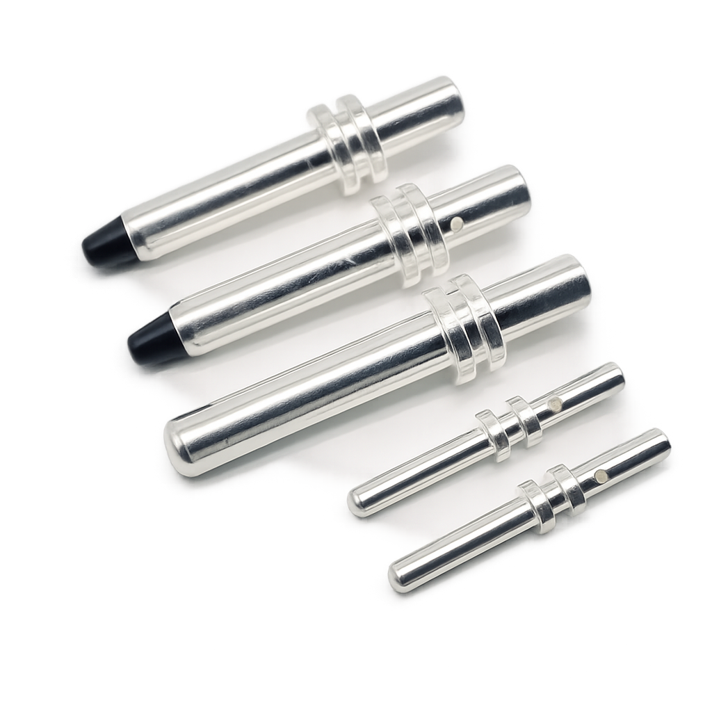

EV charging pin design parameters: inner diameter, wall thickness, pin length, and tip geometry. Essential specifications for engineers designing EV connector pins for high-current applications.
Applicable Standards
Two standards govern EV charging pin design:
- IEC 62196-2:2022/2025 — Plugs, socket-outlets, vehicle connectors and vehicle inlets. Part 2: Dimensional compatibility requirements for AC pin and contact-tube accessories. Covers Type 2 (Mennekes) connectors up to 480 V AC, 63 A three-phase / 70 A single-phase.
- UL 2251 (4th Edition) — Standard for EV plugs, receptacles, vehicle inlets, and connectors. Covers ratings up to 800 A and 1000 V AC / 1500 V DC. Applicable for North American NACS and CCS connectors.
The dimensional requirements in IEC 62196-2 ensure that pins and contact tubes from different manufacturers maintain mechanical and electrical compatibility.
Power Contact Parameters (L1, L2, L3, N, PE)
Power contacts carry the main charging current. The Type 2 connector uses five power pins derived from IEC 60309 industrial pin geometry.
| Parameter | Typical Range | Notes |
|---|---|---|
| Outer diameter | 7.5–8.0 mm | Standardized for 16–63 A range |
| Inner diameter (hollow pin) | 5.5–6.0 mm | Depends on termination method |
| Wall thickness | 0.8–1.2 mm | Must withstand crimp force without deformation |
| Contact length | 12–18 mm | Per IEC 62196-2 dimensional gauge |
| OD tolerance | ±0.05 mm | Required for pin-to-tube compatibility |
| Surface roughness (Ra) | ≤0.8 µm | Affects contact resistance and wear |
The finished pin OD tolerance of ±0.05 mm is critical — the contact tube (female side) shuts on the pin within a defined interference range. IEC 62196-2 provides specific go/no-go gauge dimensions to verify this fit.
Signal Contact Parameters (CP, PP)
The Control Pilot (CP) and Proximity Pilot (PP) contacts handle signaling per IEC 61851-1 (Annex A for PWM, Annex B for resistor-coded detection). These pins carry <1 A signal current only and are dimensionally smaller than power contacts.
| Parameter | Typical Range | Notes |
|---|---|---|
| Outer diameter | 3.5–4.0 mm | Signal-level contact size |
| Inner diameter | 2.3–3.0 mm | Smaller bore for signal wire termination |
| Wall thickness | 0.5–0.8 mm | Thinner than power contacts |
| Contact length | 10–15 mm | Typically shorter than power contacts |
| OD tolerance | ±0.05 mm | Same requirement as power contacts |
CP and PP pins must be dimensionally identical to each other — a single crimp tool and die can then be used for both signal contacts, simplifying assembly.
Crimp Barrel Design
The crimp barrel connects the machined pin to the charging cable conductor. Barrel geometry determines crimp quality, pull-out force, and long-term electrical stability.
| Parameter | Power Contact | Signal Contact |
|---|---|---|
| Barrel wall thickness | ≥0.8 mm (50–100 A) ≥1.2 mm (200 A+) |
≥0.5 mm |
| Barrel ID | Matches cable conductor OD ±0.1 mm 6 AWG (13.3 mm²): ~4.5–5.0 mm 4 AWG (21.2 mm²): ~5.5–6.0 mm |
Matches signal wire OD |
| Bore depth | ≥1.5× conductor OD or ≥12–15 mm | ≥8 mm minimum |
| Crimp compression | 10–20% reduction in barrel OD Target: 15% ±3% |
Same principle |
| Pull-out force (min) | 200 lbf (890 N) for 6 AWG 250 lbf (1110 N) for 4 AWG |
Per wire gauge |
Key requirement for tooling commonality: If pin and socket share the same crimp barrel geometry (wall thickness, ID, bore depth), a single crimping tool and die set can be used for both. This eliminates a separate tool change during cable assembly and ensures identical crimp fill across the connector pair.
Material Selection and Current Rating
Pin material determines current carrying capacity, mechanical strength, and thermal performance.
| Alloy | Composition | Conductivity (% IACS) | Application |
|---|---|---|---|
| C11000 (Cu-ETP) | ≥99.90% Cu | 100% | Standard power contacts, high conductivity |
| C18150 (Cu-Cr-Zr) | Cu + 0.5–1.5% Cr + 0.05–0.25% Zr | 80–85% | High-cycle contacts, retains hardness after crimping |
| CW617N (brass) | CuZn40Pb2 | ~26% | Structural parts, threads, low-current applications |
Current rating vs. pin outer diameter (silver-plated copper alloy, AC continuous):
- 4 mm OD — 16–20 A (signal pins, CP/PP)
- 6 mm OD — 32–40 A
- 8 mm OD — 63–70 A (Type 2 maximum)
- 10–12 mm OD — 100–200 A (DC fast-charge, CCS)
These values assume silver-plated copper alloy at 25 °C ambient. Derate for elevated temperature inside the connector housing. Actual ratings must be verified by temperature rise testing per UL 2251.
Plating
Plating protects the base metal and controls contact resistance at the pin-to-tube interface.
| Plating | Thickness | Application | Contact Resistance |
|---|---|---|---|
| Silver (Ag) over Ni strike | 2–5 µm (power) 1–3 µm (signal) |
High-current power pins, DC fast-charge | ≤0.5 mΩ |
| Gold (Au) over Ni | 0.76–1.27 µm (30–50 µ”) | CP, PP signal contacts | ≤5–10 mΩ |
| Tin (Sn) | 2–5 µm | Low-cost connectors, static connections | Higher, requires ≥100 gf contact force |
Silver plating is preferred for power contacts due to its high conductivity. A nickel underplate (1–3 µm) acts as a diffusion barrier preventing copper migration through the silver layer. Gold is standard for signal contacts where low and stable resistance over thousands of mating cycles is required.
Machining Tolerances
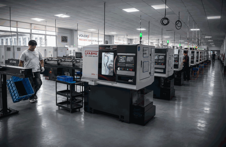
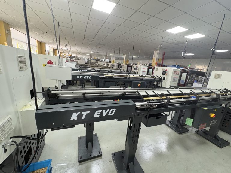
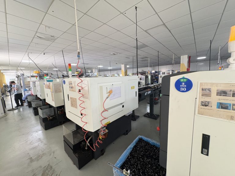
CNC Swiss turning can hold the following tolerances on charging pins:
- Outer diameter: ±0.01 mm (VOLCRIX standard)
- Inner diameter: ±0.02 mm
- Wall thickness concentricity: ≤0.01 mm TIR
- Contact length: ±0.05 mm
- Surface roughness: Ra 0.4–0.8 µm
The IEC 62196-2 dimensional compatibility gauge requires ±0.05 mm on OD for the pin to correctly engage the contact tube. Swiss turning at ±0.01 mm provides a 5× safety margin over this requirement, which is useful for silver-plated pins where plating thickness adds 5–10 µm to the finished OD.
Frequently Asked Questions
Can power and signal contacts use the same crimp tool?
Not if the barrel geometries differ. Power contacts typically use hex crimp dies sized for 6–16 mm² conductors (barrel OD ~6.5–8.5 mm). Signal contacts use smaller dies for 0.5–1.5 mm² wire (barrel OD ~2.5–4.0 mm). However, if pin and socket of the same type share identical barrel geometry, one tool can crimp both.
What is the minimum wall thickness for a 63 A charging pin?
For a 8 mm OD copper pin (63 A), wall thickness of 0.8–1.0 mm is typical. Thinner walls (≤0.6 mm) risk collapsing under crimp force or overheating at continuous rated current. When CNC turning from C11000 copper, wall thickness can be held to ±0.02 mm.
Does IEC 62196-2 specify exact pin OD values?
IEC 62196-2 provides dimensional compatibility requirements (gauge dimensions) rather than prescribing exact pin ODs. The standard ensures that a pin from any compliant manufacturer fits the corresponding contact tube. In practice, Type 2 power pins converge on 7.5–8.0 mm OD. The exact value depends on the current rating, plating thickness, and manufacturer’s design.
What plating is required for UL 2251 compliance?
UL 2251 does not mandate a specific plating type. It requires that the finished contact maintains acceptable contact resistance and temperature rise after environmental exposure (humidity, thermal cycling, salt spray). Silver over nickel is the most common combination that satisfies these requirements for power contacts.
Can brass be used for EV charging pins?
Brass (CW617N) has ~26% IACS conductivity versus 100% for copper. For the same current, a brass pin would need roughly double the cross-sectional area, making it impractical for power contacts within standardized housing dimensions. Brass is suitable for signal pins, threaded inserts, and structural connector components.
Need a custom EV charging pin design reviewed for manufacturability? Contact VOLCRIX with your drawing for a free DFM assessment.
Need custom EV charging pins for your project? View our EV charging pins manufacturing capabilities →