

EV Charging Gun Overheating: Causes and Pin Design Solutions
EV charging gun overheating solutions: causes of connector pin heating and design fixes. Learn how pin material, plating, contact resistance, and thermal management prevent overheating.
This guide examines the primary causes of EV charging gun overheating, how pin material selection, plating, and geometry influence thermal behavior, and what design engineers can do to optimize heat dissipation in high-power applications.
Ready to Start Your Project?
Free DFM review · Quote within 24 hours · Prototype in 7–15 days
Why Charging Guns Overheat — Root Causes
Heat generation in an EV charging connector follows a straightforward principle: current passing through a resistive interface produces heat proportional to I²R. The four most common contributors to excessive temperature rise are:
1. High Contact Resistance
The pin-to-tube (or pin-to-receptacle) interface is the primary source of electrical resistance in the charging circuit. While the wire and bus bar might measure under 0.1 mΩ, a poorly designed or worn connector interface can exceed 1 mΩ. At 350 A, that single milliohm produces 122.5 W of heat — concentrated in an area of a few square millimeters. The industry target for power contacts in EV charging is below 0.5 mΩ; anything above 1 mΩ is a clear overheating risk.
2. Insufficient Conductor Cross-Section
Under-sizing the charging pin diameter relative to the rated current forces current density above safe limits. A standard 6 mm DC charging pin carrying 200 A sees a current density of roughly 7 A/mm². If the same pin is used at 350 A without increasing the cross-section, the density rises past 12 A/mm², producing nearly three times the resistive heating.
3. Poor Crimp Quality
The crimped connection between the charging cable and the pin terminal is a common failure point. A loose or under-crimped joint adds resistance at the termination, generating heat that conducts back into the pin body. Pull-test verification and microsection analysis during quality control are essential to ensure crimp resistance stays below 0.1 mΩ.
4. High Ambient Temperature and Sustained Current
Even a well-designed pin will overheat if the ambient temperature at the charging station exceeds 40°C and the connector remains at full rated current for extended charging sessions. Per UL 2251, the maximum allowable temperature rise at the connector interface is 50 K above ambient. In a 40°C environment, that puts the limit at 90°C. Engineers must account for the full system thermal budget, not just the pin in isolation.
How Pin Design Affects Heat Generation
The charging pin’s physical design is the single most impactful variable for thermal management. Three parameters dominate:
Material Electrical Conductivity
Conductivity directly determines the base resistive loss in the pin body. Materials are compared using the International Annealed Copper Standard (IACS), where pure copper is 100% IACS. The most common pin alloys span a wide range:
| Material | Conductivity (% IACS) | Thermal Conductivity (W/m·K) | Typical Application |
|---|---|---|---|
| C11000 (ETP Copper) | ~101% | ~391 | High-power DC pins, bus bars |
| C18150 (CrZr Copper) | ~82% | ~325 | High-strength power contacts |
| CW617N (Brass) | ~26% | ~115 | Low-power AC pins, signal contacts |
Cross-Sectional Area
For a given current, heat generation scales linearly with resistance and therefore inversely with cross-sectional area. A pin with 50% more cross-sectional area reduces resistive heating by one-third. This is why modern 350 A CCS1 and CCS2 connectors use 8 mm or larger diameter pins with wall thicknesses optimized for both current carrying capacity and mechanical spring force.
Surface Finish and Microgeometry
Surface roughness at the contact interface reduces the effective contact area. A rough surface (Ra > 1.6 µm) creates micro-scale asperities that concentrate current, locally raising resistance and temperature. Precision Swiss-turned pins achieve surface finishes below Ra 0.8 µm, ensuring maximum metal-to-metal contact area and minimizing constriction resistance.
Thermal Management Through Material Selection
Material choice is the foundation of any thermal management strategy for charging pins. The three alloys most commonly used in EV charging applications each occupy a distinct performance tier:
C11000 — Electrolytic Tough Pitch (ETP) Copper
With conductivity exceeding 101% IACS, C11000 is the benchmark for minimizing resistive heat generation. Its high thermal conductivity (~391 W/m·K) also makes it excellent at conducting heat away from the contact interface toward the cable termination. The trade-off is mechanical: pure copper is soft and requires careful design of tube spring fingers or auxiliary spring elements to maintain consistent contact force over thousands of mating cycles.
C18150 — Chrome Zirconium Copper
C18150 offers an excellent balance of conductivity (~82% IACS) and mechanical strength. The addition of chromium and zirconium produces a precipitation-hardenable alloy with significantly higher yield strength than pure copper, while retaining roughly 80% of copper’s thermal conductivity. This makes C18150 the preferred material for high-cycle-life power contacts where both electrical and mechanical performance are critical. It is also commonly used in liquid-cooled pin designs where the material must withstand both thermal cycling and assembly stresses.
CW617N — Leaded Brass
Brass is widely used in low-cost charging connectors, but its conductivity (~26% IACS) is roughly one-quarter that of copper. At high currents, a brass pin generates approximately four times the resistive heat of a copper pin of the same dimensions. For AC charging at 16-32 A, brass can be adequate. For DC fast charging at 150 kW or higher, C18150 or C11000 is strongly recommended. The small material cost premium is quickly recovered in reduced warranty claims and improved thermal performance.
Plating and Its Role in Thermal Performance
The plating layer on a charging pin is not just for corrosion protection — it directly affects contact resistance and therefore heat generation at the interface. The three most common plating materials for EV charging pins are silver, gold, and nickel:
| Plating Material | Resistivity (µΩ·cm) | Hardness (HV) | Contact Resistance Benefit |
|---|---|---|---|
| Silver (Ag) | 1.59 | 60-120 | Lowest resistivity; conductive oxides |
| Gold (Au) | 2.24 | 50-80 | Oxidation-free; noble, but expensive |
| Nickel (Ni) | 6.99 | 200-400 | Hard, durable, non-conductive oxide layer |
Silver plating is the preferred choice for high-power EV charging pins. With the lowest resistivity of any common plating material (1.59 µΩ·cm), silver can reduce contact resistance by 20-40% compared to nickel or tin plating. A typical specification is 2-5 µm of silver over a copper or copper-alloy substrate. Silver oxide is also conductive, unlike nickel oxide, so surface tarnish does not degrade electrical performance over the connector’s service life.
Gold plating offers the advantage of being completely oxidation-free and maintaining stable contact resistance over millions of cycles. However, its high cost limits its use to signal contacts or low-power auxiliary pins, rather than the main power contacts.
Nickel plating, while durable and low-cost, has higher electrical resistivity and forms a non-conductive oxide surface. Under high current and elevated temperature, nickel-plated contacts are more likely to exhibit rising contact resistance over time — a phenomenon that accelerates thermal runaway in the connector.
Design Strategies for High-Power Applications
As charging standards push toward 500 A and beyond, several design strategies are being adopted to manage heat:
Larger Pin Outer Diameter
Increasing the pin diameter from 6 mm to 8 mm or 10 mm provides a proportional increase in both current-carrying cross-section and surface area for heat dissipation. The CCS HPC (High Power Charging) standard specifies 8 mm power contacts for 350 A continuous operation.
Thicker Wall Thickness in Tube-Style Pins
For tube-type female contacts, wall thickness determines how much copper surrounds the mating pin. Increasing wall thickness from 0.8 mm to 1.2 mm increases the thermal mass and provides a larger conductive path for heat to exit the interface zone.
Copper vs. Brass Springs
Many charging connectors use separate spring elements inside the contact tube. Specifying C18150 or beryllium copper (C17200) for these springs instead of stainless steel or phosphor bronze can reduce the overall interface resistance by 15-25%.
Liquid-Cooled Pin Designs
For ultra-high-power charging (350 kW+), passive heat dissipation is no longer sufficient. Liquid-cooled charging pins circulate dielectric coolant through channels inside or around the pin body, directly removing heat from the contact zone. These designs can sustain current levels of 500-600 A while keeping pin temperatures within UL 2251 limits. The pin material for liquid-cooled designs is almost universally C18150, which provides the necessary thermal conductivity along with the mechanical strength to withstand pressure-sealing and assembly loads.
Quality Checks That Prevent Overheating
Even the best design will fail without rigorous quality control. The following tests are essential for ensuring that charging pins deliver their designed thermal performance:
CMM (Coordinate Measuring Machine) Inspection
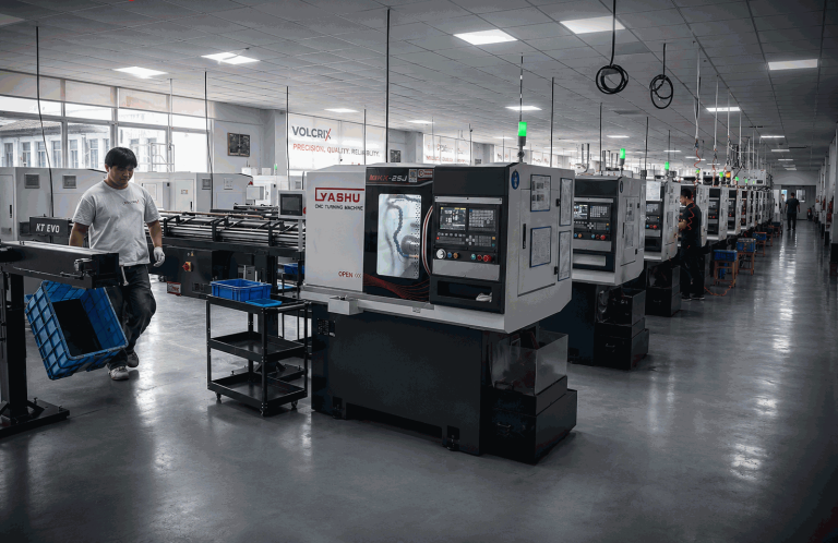
Dimensional accuracy of the pin diameter, concentricity, and mating taper must be held within micron-level tolerances. Even a 0.05 mm deviation in pin diameter can alter contact force and increase contact resistance. CMM inspection at the production level — typically sampling every batch — ensures that each pin meets its print specifications.
Contact Resistance Testing
Every power contact should be tested for milliohm-level resistance using a four-wire Kelvin measurement. The target for individual power contacts is below 0.5 mΩ. Pins that exceed 1 mΩ at the manufacturing stage will inevitably overheat in service and should be rejected.
Pull Test (Crimp Verification)
A pull test on a sample of crimped terminations verifies that the mechanical and electrical connection between the cable and the pin meets the specified pull force and resistance limits. Typical specifications call for pull forces of 500 N or higher for 50 mm² cables.
Thermal Imaging Under Load
Full thermal characterization of the assembled connector under rated current is the most definitive validation. Using a thermal camera, engineers can identify hot spots at the pin interface, along the cable termination, or at the housing joint. A properly designed pin should show a temperature rise of 30-50 K above ambient at rated current, consistent across all power contacts.
FAQ
What causes EV charging guns to overheat?
Common causes include high contact resistance at the pin-to-tube interface, undersized conductor cross-section, poor crimp quality at the cable termination, and high ambient temperature combined with sustained high-current charging. All of these increase I²R heating at the connector interface.
What is the ideal contact resistance for EV charging pins?
For power contacts in EV charging applications, the target contact resistance is below 0.5 mΩ. Values above 1 mΩ indicate excessive resistance that will generate significant heat under high current.
Does silver plating reduce charging pin temperature?
Yes. Silver has the lowest electrical resistivity of any common plating material (1.59 µΩ·cm) and forms a conductive oxide. A 2-5 µm silver plating can reduce contact resistance by 20-40% compared to nickel or tin plating.
What is the maximum safe temperature for an EV charging pin?
Per UL 2251, the maximum temperature rise at the connector interface is 50 K above ambient. For a 40°C ambient, the pin surface should not exceed 90°C.
Can brass pins be used for high-power DC charging?
Standard brass (CW617N, ~26% IACS) has significantly lower thermal conductivity than copper or chrome zirconium copper. For 150 kW+ DC charging, C18150 or C11000 is strongly recommended to manage heat dissipation.
Related: material conductivity and heat generation
Related: connector standards and current ratings
Ready to Start Your Project?
Free DFM review · Quote within 24 hours · Prototype in 7–15 days
Experiencing overheating issues with your charging pins? Contact VOLCRIX for custom pin design solutions →
Need custom EV charging pins for your project? View our EV charging pins manufacturing capabilities →