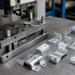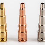

Anodized Stamped Brackets: Final Interface Review Before Shipment
Direct answer: A final interface review for anodized stamped brackets checks eight things, not one. Coating thickness at defined points, dimensional change on every mating feature, masking integrity on threads and grounding points, colour against a master sample, seal quality, edge and hole coverage, hardness where Type III applies, and the pre-coat dimension record. The most common failure is a bracket that passes coating inspection and fails assembly because the oxide consumed the fit tolerance.
Need Anodized Stamped Brackets?
Type II / III · Interface review · CMM + gauge report · Quote in 24h
Why Interface Review Is a Separate Step
Anodizing inspection asks: is the coating there, right colour, sealed. Interface review asks a different question: does this part still assemble. Two different checklists, and only the first is usually documented.
The gap shows at assembly. A bracket arrives with a perfect 15-micron coating. The bore, dimensioned 10.00 +0.02/-0, now measures 9.985 because the oxide grew inward. The pin will not enter. Nothing on the coating certificate is wrong.
How Oxide Growth Changes Dimensions
The oxide converts aluminium into aluminium oxide. Roughly half the thickness sits outside the original surface and half consumes the base metal. Every surface moves, and the direction depends on whether it is an external face or a bore.
| Coating | Typical Thickness | Growth per Surface | Effect on a 10 mm Bore |
|---|---|---|---|
| Type II, Class 1 | 5-10 µm | ~2.5-5 µm | Bore shrinks 5-10 µm |
| Type II, Class 2 | 10-25 µm | ~5-12.5 µm | Bore shrinks 10-25 µm |
| Type III hardcoat | 25-50 µm | ~12.5-25 µm | Bore shrinks 25-50 µm |
Against a typical fit: a 10 mm H7 bore is +0.015/0. A Class 2 Type II coating shrinks it up to 0.025 mm — the entire band and more. A sliding pin becomes interference.
The fix is not to change the anodizer. It is to dimension the part pre-coat and state the coating growth allowance on the drawing, or to mask the bore. Both work. Neither happens by default.
The Eight Interface Checks
| # | Check | Method | Failure Mode If Skipped |
|---|---|---|---|
| 1 | Coating thickness at defined points | Eddy-current per ISO 2360, or coating mass per ASTM B137 | Bare or thin spots at recesses and hole edges |
| 2 | Dimensional change on mating features | CMM post-coat vs pre-coat record | Pin will not enter, or free fit becomes interference |
| 3 | Masking integrity | Thread go/no-go, electrical resistance on grounding points | Anodized threads chip on assembly; no electrical path |
| 4 | Colour against master | Spectrophotometer, ΔE to master sample | Batch mismatch visible on assembled product |
| 5 | Seal quality | Dye stain test per the specified standard | Coating stains and corrodes in service |
| 6 | Edge and hole coverage | Visual at 10x on stamped edges and pierced holes | Bare sheared edges become corrosion initiation sites |
| 7 | Hardness where Type III | Microhardness per the applicable standard | Wear resistance claim not met |
| 8 | Pre-coat dimension record | Inspection report comparison | No way to separate stamping drift from coating growth |
Check 6 in Detail: Stamped Edges
This is where stamped brackets differ from machined ones, and where anodizing programs quietly fail.
A sheared edge has a different structure from the parent sheet — burnished zone, fracture zone, burr. Oxide growth is uneven, and at a sharp burr the coating can be discontinuous. That bare edge is where corrosion starts, usually inside a pierced hole where nobody looks.
Two controls: a maximum burr height — typically 0.05 mm — and edge coverage inspection at 10x on a defined sample. A tumbled edge anodizes far more consistently than a raw shear.
Colour Consistency: What Can Actually Be Controlled
Batch-to-batch colour variation is normal, driven by alloy lot chemistry, bath drift and dye concentration. Clear varies least; black and bronze most.
What a buyer can control: one alloy source per program, a signed physical master sample, a ΔE limit to that master (typically 1.5-2.0 for architectural), a stated light source (D65), and one anodizer per program. Splitting between two lines guarantees a mismatch at assembly.
What cannot be controlled: exact match across alloy lots, or across Type II and III. If your program needs both on mating parts, expect a visible difference and design for it.
What VOLCRIX Handles, and What We Do Not
In-House and Coordinated Capability
- Stamping and forming — 40 presses 5-200 tons, progressive die, burr to 0.05 mm
- Deburring — tumbling and vibratory finishing before coating
- Anodizing coordination — qualified Type II and III partners, thickness and seal verified
- Pre-coat dimension record — CMM before coating, retained for comparison
- Post-coat interface review — the eight checks above, documented per lot
- Colour control — master sample, ΔE, one alloy source per program
We do not operate an anodizing line. Brackets are anodized by qualified partners, and we hold the interface review responsibility and issue the report. If your program requires anodizing under one roof, say so at quoting.
Not offered: closed-die forging, casting, or anodizing assembled parts containing other metals.
About VOLCRIX
VOLCRIX has made precision metal components in Yueqing, Wenzhou since 1991 — 35 years. 40 stamping presses 5-200 tons, 60+ Swiss machines, 3/4/5-axis CNC.
ISO 9001:2015 and IATF 16949. Spectrometer per heat lot, Zeiss CMM. 500+ customers in 40+ countries.
Frequently Asked Questions
How much does anodizing change a stamped bracket dimension?
The oxide grows both outward and into the substrate. Roughly half the coating thickness is added to the outside surface and half consumes the base metal. For a 15-micron Type II coating, expect about 7 to 8 microns of growth per surface.
Should I anodize before or after forming?
Form after anodizing only at very large bend radii. Anodized aluminium has a brittle oxide layer that crazes at the bend, and cracks expose bare metal as corrosion sites. For anything with a bend radius under about 3 times material thickness, form first, then anodize.
What tolerance should I put on an anodized bracket in the drawing?
Specify pre-anodize dimensions with the full machining tolerance and add a note that final dimension applies after coating, or specify pre-coat dimension and the coating ranges. The second is safer.
Why does the anodized colour vary between batches?
Three inputs: alloy lot (silicon, copper and iron traces shift the response), bath chemistry drift, and dye concentration. Clear anodizing varies less than dyed.
What should a final interface review of anodized brackets cover?
Eight items: coating thickness at defined points, dimensional change on mating features, masking integrity on threads and grounding points, colour match against the master, seal quality, edge and hole coverage, hardness if Type III, and the pre-coat dimension records.
Need Anodized Stamped Brackets?
Type II / III · Interface review · CMM + gauge report · Quote in 24h
Related Pages
Standards Referenced
- MIL-A-8625 — Type I, II, III
- ASTM B137 — coating mass per unit area
- ASTM B580 — anodizing of aluminium
- ISO 2360 — eddy-current thickness
- AAMA 611 — colour