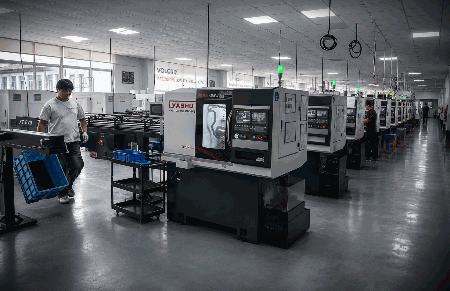

Surface Mount vs Through-Hole Connector Pins for EV Charging Applications
Surface mount (SMT) vs through-hole connector pins for EV charging: compare PCB assembly methods, mechanical strength, current handling, and when to choose each for your charging connector design.
Through-Hole (THT) Pin Design
Through-hole pins are inserted into drilled holes in the PCB and soldered on the opposite side. The solder joint wraps around the pin barrel and fills the annular ring, creating a mechanical interlock that is substantially stronger than a surface-bonded joint. This design has been the workhorse of power electronics for decades.
Key characteristics:
- Current capacity: 5–200 A per pin, depending on pin diameter and cross-section. A typical 2.0 mm diameter THT pin in an EV charging connector can handle 40–60 A continuously.
- Mechanical strength: Pull force typically exceeds 50 N. The through-hole solder joint distributes stress along the barrel length rather than concentrating it at the pad interface.
- Thermal dissipation: The pin barrel conducts heat through the PCB via the plated through-hole, improving heat spreading compared to SMT pads alone.
- Vibration resistance: Excellent — the mechanical interlock resists shear and pull forces from cable strain and vehicle vibration (MIL-STD-202 test methods).
- Assembly cost: Higher — requires drilling, pin insertion (manual or selective), wave soldering or selective soldering, and additional inspection steps.
THT is the preferred termination for power contacts in EV charging connectors where current exceeds 20 A and mechanical retention is critical.
Surface Mount (SMT) Pin Design
Surface-mount pins sit directly on PCB pads and are reflow soldered alongside other SMD components. The pin has a flat or gull-wing base that contacts the pad, and the solder joint forms exclusively on the pad surface. No drilling is required, and components can be placed on both sides of the board.
Key characteristics:
- Current capacity: 1–30 A per pin. The upper range is achievable with wide pad geometry, multiple solder fillets, and thermal via arrays. Beyond 30 A, SMT pins risk pad lifting under thermal cycling.
- Mechanical strength: Pull force depends entirely on PCB pad adhesion and solder fillet volume. Typical values range 15–40 N on standard FR-4, with higher values achievable on boards with reinforced pad anchoring.
- Thermal dissipation: Primarily through the pad and thermal vias. Requires intentional via stitching for high-power applications.
- Vibration resistance: Moderate — acceptable for signal contacts but may require adhesive underfill for high-reliability applications.
- Assembly cost: Lower — reflow soldering is a single-step process compatible with standard pick-and-place lines. No drilling, wave soldering, or selective soldering needed.
- Reflow temperature: 230–260 °C (typical SAC305 solder profile), which limits compatible plating materials and pin geometries.
SMT is the dominant choice for signal and communication pins (CP, PP, proximity detection) in modern EV connectors, and for space-constrained designs where double-sided PCB population is beneficial.
Comparison Table: SMT vs THT for EV Charging Pins
| Parameter | Through-Hole (THT) | Surface Mount (SMT) |
|---|---|---|
| Current capacity (per pin) | 5–200 A | 1–30 A |
| Mechanical strength (pull force) | >50 N (typical) | 15–40 N (pad-dependent) |
| Assembly cost | Higher (drill, insert, wave solder) | Lower (reflow, one pass) |
| Rework difficulty | Moderate (requires solder wick + desoldering) | Higher (pad damage risk, lifted pads) |
| PCB area used | Larger (hole + annular ring on both sides) | Smaller (pad only on one side) |
| Thermal dissipation | Better (barrel conducts through board) | Via-dependent (requires intentional thermal vias) |
| Vibration resistance | Excellent (mechanical interlock) | Moderate (pad adhesion only) |
| Automated handling | Separate process (selective/wave) | Fully compatible (pick-and-place + reflow) |
| Double-sided PCB | Limited (components on solder side interfere) | Fully supported |
| Typical applications | Power contacts, DC+/DC−, ground | CP, PP, proximity, communication signals |
When to Use THT for Charging Connector Pins
Through-hole termination is the correct choice when any of the following conditions apply:
- Power contacts exceeding 20 A: CCS and NACS DC power pins (DC+, DC−, and ground) typically carry 100–500 A in fast-charging scenarios. Only THT pins with appropriate cross-section can handle this current density reliably over thousands of thermal cycles.
- High-vibration environments: Vehicle-mounted charge inlets experience road vibration, cable whip, and connector insertion/removal forces. THT’s mechanical interlock passes MIL-STD-202 vibration testing (10–2000 Hz, 20 G) without fatigue failure at the solder joint.
- Components requiring high mechanical retention: Charging connector pins experience repeated insertion and withdrawal forces (up to 100 N in some standards). THT pins maintain positional stability over 10,000+ mating cycles where SMT pins may shift or lift.
- High-temperature cycling applications: The thermal expansion mismatch between pin (brass/copper) and PCB (FR-4) is better accommodated by a through-hole solder joint than a surface fillet.
When SMT Makes Sense for Signal Pins
Surface-mount termination is increasingly adopted for non-power contacts in EV connectors:
- CP/PP signal contacts (<1 A): The Control Pilot and Proximity Pilot contacts in CCS and NACS connectors carry signalling voltages at microampere currents. SMT is ideal for these low-current, low-stress pins.
- Space-constrained designs: Charging handles and portable EVSE units benefit from SMT’s smaller footprint and double-sided PCB capability. Eliminating through-holes frees routing space on inner layers.
- High-volume automated assembly: A single reflow pass processes all SMD components — including connector pins — on the same line. This reduces cycle time and labour cost compared to THT’s multi-step process.
- Double-sided PCB layouts: Signal conditioning circuitry (CP/PP filtering, isolation amplifiers, communication transceivers) can be placed on the opposite side of the PCB from the connector, reducing overall board size by 20–30%.
- Reduced risk of solder defects: SMT reflow is a controlled, repeatable process. Voiding rates in SMT solder joints are typically <5%, compared to wave solder voiding that can reach 15–25% in THT barrel joints.
Hybrid Approaches in Modern EV Connectors
Contemporary charging connector designs increasingly adopt a hybrid strategy that combines the strengths of both technologies on a single PCB:
- CCS (Combined Charging System): Modern CCS inlets use THT pins for the DC power pair (DC+ and DC−) rated at 350–500 A, while CP, PP, and communication pins (CAN bus, Ethernet) use SMT gull-wing terminals on the same PCB. This optimises current capacity where it matters most and assembly efficiency for the remaining contacts.
- NACS (North American Charging Standard): The NACS connector, now adopted across major North American OEMs, employs a similar split: THT for the high-current power pins and the ground pin, with SMT for the CP, PP, and thermistor sense lines. The compact form factor of NACS particularly benefits from SMT signal pins to minimise PCB dimensions.
- GB/T and CHAdeMO: Chinese and Japanese fast-charging standards follow the same principle — power pins are through-hole, while auxiliary contacts are surface mount. Some CHAdeMO implementations use press-fit THT for power, avoiding solder entirely for the highest-current paths.
A common PCB layout strategy places the THT power pins along one edge of the board with wide copper pours and thermal relief, while SMT signal pins populate the remaining area with standard reflow-compatible geometry. This hybrid board is processed with a THT-compatible solder mask dam between the two zones to prevent solder bridging during wave soldering.
Plating Considerations for SMT vs THT
Pin plating has a direct impact on solder joint reliability and process compatibility:
- THT pin plating (Sn over Ni): The standard finish for through-hole power pins is matte tin (Sn) over a nickel (Ni) underplate. Tin provides excellent wetting with SnPb and lead-free wave solder alloys. Minimum tin thickness of 5–10 µm is recommended for reliable barrel fill. The nickel barrier (1–3 µm) prevents copper-tin intermetallic growth that would weaken the joint over thermal cycling.
- SMT pin plating (Sn/Ag or matte Sn): For reflow soldering at 230–260 °C, SAC305 (Sn96.5/Ag3.0/Cu0.5) solder paste wets well to matte tin or Sn/Ag finishes. Pure tin with a minimum thickness of 3–5 µm is sufficient for SMT reflow. Thicker tin can lead to solder beading and tombstoning on small pins.
- Gold plating incompatibility: Gold flash (≥0.5 µm) on pin contact surfaces is often specified for low-resistance mating interfaces. However, gold on the termination/solder area is problematic: gold dissolves rapidly into molten solder, forming brittle AuSn₄ intermetallics that degrade joint strength. For SMT reflow, gold thickness must be kept below 0.1 µm on solderable surfaces, or the gold must be selectively plated (masked) to expose the solderable underlayer. THT wave soldering is somewhat more forgiving of gold on the barrel, but selective gold removal or ENIG termination pads remain best practice.
- Solderability shelf-life: THT pins with Ni/Sn plating maintain solderability for 12+ months under normal storage. SMT pins intended for reflow should be evaluated for solderability after steam-age testing (8 hours at 93 °C/100% RH per J-STD-002) to ensure no oxidation has occurred that would impede wetting.
FAQ
Can I use SMT pins for power above 30 A in an EV charging connector?
It is not recommended. Above 30 A per pin, SMT solder joints experience accelerated thermal fatigue from CTE mismatch and risk pad lifting. THT pins provide the mechanical interlock and thermal dissipation required for reliable operation at high currents. Some designs use multiple SMT pins in parallel for current sharing, but this increases pad stress and introduces current imbalance risks. For power contacts above 20 A, THT remains the industry standard.
Is the assembly cost difference between SMT and THT significant in production?
Yes. SMT assembly (reflow soldering) costs approximately 30–50% less per joint than THT assembly (drilling + insertion + wave soldering) in high-volume production. The savings come from fewer process steps, no drilling cost, and compatibility with standard pick-and-place equipment. However, for low-volume production (<1000 units), the tooling cost difference is minimal and THT may be more practical given simpler inspection and rework requirements.
Does SMT vibration performance improve with adhesive underfill?
Yes. Applying a UV-cure or heat-cure epoxy underfill beneath SMT pins can increase pull force by 2–3× and dramatically improve vibration fatigue life. Underfilled SMT joints have passed MIL-STD-202 vibration testing (20 G, 10–2000 Hz) in several EV connector qualification programs. However, underfill adds a process step and material cost of approximately $0.02–$0.05 per pin, reducing the cost advantage of SMT.
What pin plating is best for a hybrid SMT/THT connector PCB?
For hybrid boards containing both SMT signal pins and THT power pins, the recommended approach is: matte tin over nickel (Sn/Ni) on THT power pins for wave solder compatibility, and selective gold (on the mating contact area only) with a Sn or SnAg finish on the SMT termination surfaces. Alternatively, use ENIG (Electroless Nickel Immersion Gold) PCB pads for SMT locations and OSP (Organic Solderability Preservative) for THT pads. Coordinate with your pin manufacturer — such as VOLCRIX — to ensure termination finishes are optimised for your specific assembly process.
Get Precision EV Charging Pins
Designing a charging connector PCB? Get precision pins for SMT or THT from VOLCRIX →
Need custom EV charging pins for your project? View our EV charging pins manufacturing capabilities →