
Precision Shaft Prototyping: From CAD Drawing to First Article Inspection
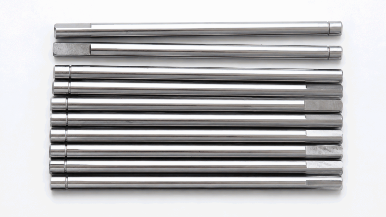
Direct answer: Precision shaft prototyping turns a 2D drawing or 3D CAD model into a small batch (typically 5-50 pieces) of functional parts within 7-15 working days, allowing the buyer to validate fit, finish, concentricity, and material behavior before committing to production tooling or a 10,000-piece run. VOLCRIX prototypes precision shafts on 60+ Japanese Star Swiss turning machines and CNC turning centers with plus minus 0.01 mm OD tolerance, full Zeiss CMM first-article inspection, and IATF 16949 traceability from prototype through PPAP. We routinely ship prototype shafts in 303/304/316L stainless, C3604 brass, C11000 copper, 4140/4340 alloy steel, and aluminum 6061/7075 within 7-10 working days for drawings released as STEP or PDF with GD&T.
Common Applications for Prototyped Precision Shafts
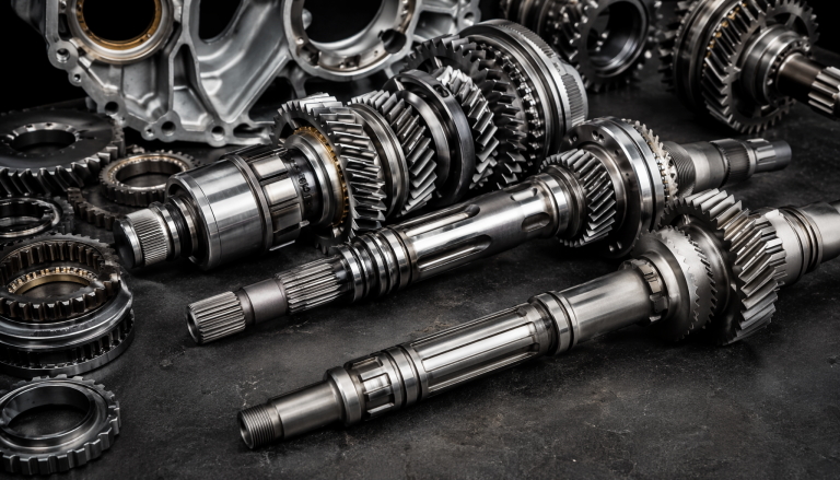
- Motor and gearbox shafts (electric motor rotors, planetary gear pinions, drive shafts): prototype batches of 10-50 pieces in 4140 alloy steel or 17-4 PH stainless, with centerless grinding, induction hardening, and surface finish Ra 0.4 or better for bearing journals.
- Pump and fluid-handling shafts (centrifugal pump shafts, hydraulic piston shafts, mixer shafts): 316L stainless prototype shafts with polished surfaces (Ra 0.2-0.8) for seal interfaces, magnetic-particle inspected per ASTM E709.
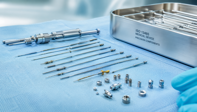
- Medical and dental instrument shafts (surgical tool shafts, dental handpiece mandrels, implant driver shafts): 316LVM or 17-4 PH H900 stainless, electropolished to Ra 0.2, with full lot traceability per ISO 13485 audit pack.
- EV drivetrain shafts (e-axle intermediate shafts, half-shafts, rotor shafts): prototype 4140 induction-hardened shafts or 40CrMnMo alloy steel with plus minus 0.005 mm bearing journal tolerance and runout under 0.01 mm.
- Industrial automation lead screws and ball screw shafts: prototype 50CrMo4 (DIN 1.7228) ground lead screws with 0.05 mm lead accuracy, induction hardened to HRC 55+ on the thread flanks.
- Connector and receptacle pin shafts (IEC 62196 charging pins, M12/M8 industrial connector pins, D-sub machined contacts): C18150 CuCrZr or C11000 copper prototype pins with selective silver plating, plus minus 0.01 mm OD tolerance.
Manufacturing Support from VOLCRIX
- Material sourcing in bar, hex, and pre-cut billet: 303/304/316/316L stainless (ASTM A484), 4140/4340 alloy steel (ASTM A29), C3604 brass (ASTM B16), C11000 ETP copper (ASTM B152), 6061-T6/7075-T6 aluminum (ASTM B211), and customer-specified plastics such as PEEK and Delrin.
- Prototype machining on Star SR-20R / SR-38R Swiss turning centers and Citizen L20/L32 sliding-head machines, plus 3-axis VMC milling for features that exceed Swiss turning capability (slots, flats, off-axis cross-holes).
- Inline OD tolerance plus minus 0.01 mm verified by Zeiss CMM (PRISMO) and OGP optical comparator on every first-article batch; concentricity, runout, and perpendicularity all measurable to ISO 1101:2017.
- In-house secondary services: centerless and cylindrical grinding (Ra 0.2-0.8), induction hardening (up to HRC 60), electropolishing, passivation per ASTM A967, and plating coordination (silver, tin, nickel, gold, chrome, black oxide).
- First-article inspection report (FAIR) per AS9102 or customer template; PPAP Level 1-3 documentation for automotive programs; IMDS and REACH/RoHS declarations supported.
Precision Shaft Prototyping Buyer Checklist
- Release the controlling drawing package: 2D PDF with GD&T (ISO 1101:2017 symbols preferred over ASME Y14.5 unless the program is North American), 3D STEP or IGES, material spec with revision, and document precedence statement. State whether the 3D model or the 2D drawing controls tolerances.
- Mark all critical-to-function (CTF) features: bearing journals, seal surfaces, thread engagement zones, splines, mating diameters, runout-critical features. Each CTF feature needs an explicit datum and tolerance zone; a generic note like “precision” is not a substitute.
- Specify state of dimensions: are they before or after plating, before or after heat treatment, after grinding, or in the final supplied condition? Hardening plus plating changes functional size by 0.005-0.02 mm depending on the layer stack.
- Provide quantities, intended use, and inspection scope: prototype (5-50 pcs), pre-production pilot (100-500 pcs), or full production (1k+)? Will the prototype be functional-tested, or is dimensional conformance the gate? This drives FAIR scope and inspection cost.
- Confirm change-control expectations before approval: which changes (material brand, bar supplier, machine program revision, sub-supplier finish) require buyer notification? For IATF programs, every change typically triggers PPAP revalidation; for prototype, a documented change log is usually acceptable.
Related Custom Manufacturing Services
Custom Swiss Turning Parts | Sourcing CNC Turned Parts from China | Precision Pin Manufacturing | Connector Pin Manufacturing Guide
Prototype-to-Production Transition: What Changes Between Sample and 1000-piece Run
A common mistake in Chinese shaft sourcing is approving a prototype that was produced with extra inspection, slower cutting parameters, selected bar stock, or manual deburring that does not scale. Before promoting prototype to production, the buyer should confirm which route, tooling, fixtures, inspection frequency, deburring, washing, packaging, and subcontracted operations will be used in the released condition. Open assumptions should be written into the purchase order rather than disappearing between sample and order.
The four specific items to review at the prototype-to-production transition gate are:
- Bar stock identity and condition: prototype often uses selected bar stock (cleaner surface, tighter chemistry). Production must specify the actual mill heat, bar size, and condition (cold drawn, hot rolled, centerless ground) that will be procured at volume.
- Tooling strategy: prototype may use a single-point tool changed every shift. Production needs a tool-life strategy (e.g. Sandvik Coromant inserts, replaced every 200 pieces) with offset authority defined for the operator.
- Inspection frequency: prototype often measures 100% of CTF features. Production usually moves to AQL sampling (typically 1.0/4.0) with control charts for SPC. Confirm the sampling plan, the gauge, and the reaction rule.
- Sub-supplied processes: heat treatment, plating, and grinding are often outsourced. Confirm the sub-supplier list, their certifications (ISO 9001, NADCAP for heat treat), and the change-control terms that propagate when the sub-supplier changes a bath or furnace.
Common Prototype Shaft Defects and Their Root Causes
| Defect | Likely cause | Prevention |
|---|---|---|
| Excessive runout on bearing journal | Insufficient support during turning; chuck runout; thermal growth | Use steady rest; specify chuck class; warm up machine before final cut |
| Burr inside cross-hole | Drill geometry; chip evacuation; tool wear | Use high-helix drill; peck-drill cycle; deburr with abrasive brush, not hand tool |
| Surface roughness above spec | Wrong feed rate; worn insert; inadequate coolant | Reduce feed to 0.05 mm/rev; replace insert; verify coolant flow |
| Hardness drift after heat treatment | Furnace temperature variation; rushed quench | NADCAP-certified heat treater; thermocouple on every batch; sample 3 pcs per lot |
| Thread class out of spec | Wrong pitch; worn tap; chip in thread | Use calibrated ring/plug gauge; replace tap every 50 holes; chip-control coolant |
FAQ: Precision Shaft Prototyping
What is the typical lead time for a precision shaft prototype?
VOLCRIX ships 5-50 piece prototype batches in 7-10 working days for drawings released as STEP or PDF with GD&T. Lead time assumes bar stock is in inventory or available from local mills (304/316 stainless, C3604 brass, 4140 steel, 6061 aluminum). Exotic alloys (17-4 PH H900, Inconel, titanium) add 5-15 working days for material sourcing. Plating or heat treatment adds another 3-5 working days if outsourced.
What tolerances can VOLCRIX achieve on prototyped precision shafts?
Standard Swiss turning holds plus minus 0.01 mm on OD and plus minus 0.02 mm on length. Centerless grinding after turning tightens OD to plus minus 0.0025 mm and surface finish to Ra 0.2-0.4. Concentricity and runout are typically 0.005-0.01 mm on turned features and under 0.005 mm on ground features. Tight-tolerance features (plus minus 0.001 mm) require CMM grinding and are quoted separately.
Should I send a 2D drawing or 3D STEP file for the prototype?
Send both. The 2D drawing controls GD&T, surface finish notes, material spec, and revision. The 3D STEP file is used to verify the supplier understood the geometry and to run CAM tool paths. State explicitly which document controls if the two disagree. For tight-tolerance programs, also send a PDF with callouts of the CTF (critical-to-function) features you want inspected on the FAIR.
How many prototype pieces should I order?
5 pieces is enough to confirm dimensional conformance. 10-20 pieces is typical for assembly fit checks and functional testing. 50 pieces is the standard pre-production pilot before committing to 1,000-piece production. For automotive programs, the typical PPAP Level 3 sample size is 30 consecutive production pieces.
Does VOLCRIX provide first-article inspection with prototypes?
Yes. Every prototype batch ships with a FAIR per AS9102 (or customer template) listing every characteristic called out on the drawing, the measured value, the gauge used, and the pass/fail result. FAIR is generated on Zeiss CMM PRISMO and OGP optical comparator. PPAP Level 1-3 packages are available for automotive programs.
Can I get a quote within 24 hours?
Yes, if you send the 2D drawing (PDF), 3D STEP file, material spec, quantity, and any plating or heat-treat requirements. VOLCRIX quotes 80% of RFQs within 8 working hours during China business hours. Exotic alloys or programs requiring DFM review may take 24 hours. The quote includes material cost, machining time, secondary operations, inspection, and packaging.
What materials can VOLCRIX source for prototype shafts?
Stainless steel (303, 304, 316, 316L, 17-4 PH, 904L), carbon and alloy steel (1018, 1045, 4140, 4340, 8620), tool steel (D2, M2, A2), aluminum (6061, 7075, 2024), brass (C3604, C260, C272), copper (C11000, C18150 CuCrZr), bronze (C932, C954), titanium (Grade 2, Grade 5 Ti-6Al-4V), and engineering plastics (PEEK, Delrin, PTFE). In-house spectrometer verifies chemistry on every heat before cutting.
How do I transition from a 50-piece prototype to a 5,000-piece production run?
Before approving production, walk through the DFM review, confirm the production bar-stock source, lock the tooling strategy, agree on AQL sampling, and document the change-control terms in the PO. VOLCRIX provides a “prototype-to-production transition document” that lists every assumption in the prototype run that must be replicated or revalidated at production. For automotive programs, PPAP Level 3 is the standard handover.